Handling
CAD data in VDAFS format
VDA
surface interface (VDAFS)
VDAFS is an interface to exchange data between
different CAD systems or to exchange data between CAD systems and other
applications, where the data exchange of free surfaces and bounded surfaces is
especially important.
VDAFS is developed by the Association of
Automobile Industry (VDA). For a detailed documentation of the interface see
DIN 66301.
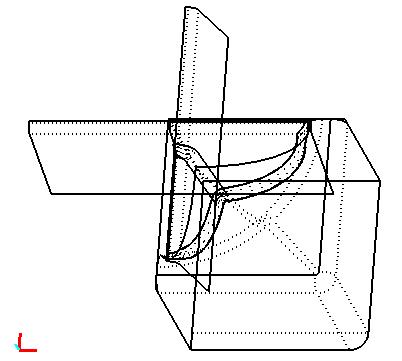
Following picture shows a CAD model of a
container built out of 8 bounded surfaces (see demo file vdafs.vda) .
Using MAKROS-A following types of VDAFS
elements can be read from a VDAFS input file and used to generate a finite
element model:
POINT: (x,y,z)-
coordinates of single points
PSET: sequence
of single points
CIRCLE: arc
of a circle
CURVE: curve
in 3D space
CONS: curve
on a free surface
SURF: free
surface in 3D space
FACE: bounded
surface
MAKROS-A especially provides methods to
generate interactive macro elements on bounded surfaces (see demo file
“vdafs.dem”).
Handling
of different VDAFS element types with MAKROS-A
POINT, PSET, CIRCLE, CURVE
VDAFS elements of type POINT and PSET are
handled in MAKROS-A as point elements
(element type 1), they can be used to transfer coordinates of single points.
VDAFS elements of type CIRCLE and CURVE are approximated by one or more macro
elements of type 22 (arc element).
FACE and SURF
Bounded surfaces are defined in VDAFS as free
surfaces (SURF element) wit one or more closed curves (CONS elements) on the
surfaces. SURF elements and CONS elements mostly consist of more than one
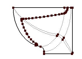
segment. Plotting SURF elements, inner edges of segments are shown as dotted
lines. Following picture shows one SURF and CONS element together with automatically
generated nodes at the corners of SURF segments and CONS segments:
The generation of macro elements on one bounded
surface is done in MAKROS-A by the following steps:
1) Generate nodes on the surface. There are
different means to do this (see dialog “Node generation”).
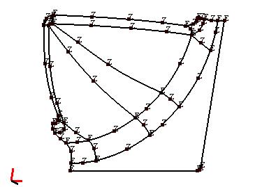
2) Define macro elements using these nodes (see
dialog “Element definition”). It is important that macro
elements of neighbouring surfaces use on the common edge nodes that have nearly
identical coordinates. Generating the entire macro model, these nodes are
merged into one single node. To identify nodes of macro elements of
neighbouring surfaces, corner nodes of macro elements are marked by the symbol
“E” and intermediate nodes on the edges of macro elements are marked by the
symbol “Z”. Following picture shows the macro elements of two neighbouring
surfaces where the defining nodes are marked “E” or “Z” respectively:
3) Generate a macro model (see dialog “Macro- / FE structure”). After all VDAFS surfaces have
been approximated by macro elements, the entire macro model is generated using
the macro elements of all surfaces, where the nodes on the edges of
neighbouring surfaces are merged into one node, if they have equal coordinates
within a given tolerance.
4) Subdivide the macro elements into finite
elements. This is done as with an ordinary macro model (see chapter
“Subdivision of macro elements into finite elements”).
5) Smooth the finite element model if necessary
(see dialog “Macro-
/ FE structure”).
The calculation of finite element nodes when subdividing the macro elements is
done by C0 – Coons interpolation between opposite edges of the macro element.
Depending on how large and strongly curved the macro elements are, the
generated nodes will differ from the geometry of the originating SURF element.
This difference may be eliminated by smoothing the finite element model. The following
algorithm is used: For each macro element an optimal plane is determined, where
the nodes of the finite elements belonging to the macro element are projected.
Then, nodes on the originating SURF element are calculated, that have the same
projection on the plane. These nodes on the SURF element replace the finite
element nodes calculated by the Coons
interpolation. To determine an optimal plane, no small macro elements must be
used, also the macro elements must not be to strongly curved.
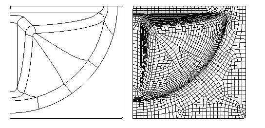
Following picture shows the generated macro
model and final finite element model of the container shown above (see demo
file “vdafs.dem”).
Dialogs
to handle VDAFS data
The dialogs to handle VDAFS data are grouped
together in a window using the following pages.
|
Read VDAFS input file, save data to or load
from a binary file |
|
|
Plot VDAFS elements |
|
|
Generate nodes on bounded surfaces |
|
|
Define macro elements on SURF elements |
|
|
Generate a macro and FE model, smooth the FE
model |
|
|
Define a VDAFS element selection, remove
VDAFS elements |
The window is activated by the command “VDAFS data” in the menu group “Generation” and deactivated using button “Cancel”.
As long as the window is active all other
commands to modify the macro or finite element model are disabled.
Attention: Before a new VDAFS input file is
read or a VDAFS binary file is loaded, all data that is actually in memory
(macro model, FE model, VDAFS data etc.) is removed and must eventually be saved
to disk. If several VDAFS files shall be combined in one finite element model,
first one macro and FE model must be generated for each VDAFS file. Then, these
structures can be combined in one structure using command “Load structure”.