Subdivision
pattern
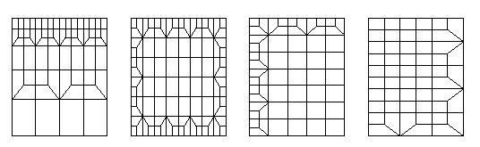
Each subdivision of triangular or quadrilateral
macro elements is based on a pattern. Regular patterns subdivide opposite edges
with the same number of segments, as is shown in the following figure:
For irregular patterns at least 2 opposite
edges have a different number of segments. This way a mesh refinement is
achieved into one or two directions. A 2 digit ID distinguishes the patterns
for regular and a 3 digit ID for irregular subdivisions. The pattern ID for
regular subdivisions is 20 for macro elements 20-25, 30 for macro elements
30-35,60-65 and 40 for macro elements 40-45,80-85.
Besides the pattern ID the number of
intermediate nodes for the edges of the macro element must be given.
With some patterns also a quotient q for the
length of last to first FE edge can be given. The length of FE edges increases
linearly for q > 1 and decreases linearly for q < 1.
In case
of solid elements a pattern is always applied to the bottom and the top
surface. The direction perpendicular to the bottom surface will always be
regularly subdivided, for this direction, the number of intermediate nodes and
optionally a quotient for last to first FE edge length must be given.
Following m1,m2,m3,m4 are the number of
intermediate nodes for edges 1-4 of a quadrilateral macro element, where the
edges are numbered counter clock wise beginning with the first element node.
Direction R1 points from first to second node and direction R2 from second to
third node.
With a regular pattern only values for m1 and
m2 must be given, m3 = m1 and m4 = m2 are set automatically. Also quotients q1
and q2 for the two main directions of a quadrilateral macro element may be
given.
With an irregular pattern the last two digits
of the pattern ID define the subdivision pattern as shown in the following pictures. The first digit of
the pattern ID determines the rotation of the pattern. The pattern is first
applied to an unit element and is then mapped to the geometry of the macro
element, where the first digit of the pattern ID gives the node of the macro
element that coincides to the first node of the unit element.
Following pictures show the different
subdivision patterns.
Pattern
101, 102, 104, 105
With pattern 101 and 102 a linear increase of
the number of intermediate nodes is applied for direction R1 towards direction
R2. The number of intermediate nodes for edge 1 (m1) and edge 2 (m2) must be
given, m3 = m1+m2+1 and m4 = m2 are set.
With patterns 104 and 105 also m3 must be
given, with abs(m3-m1) < m2. The smaller number of intermediate nodes will
at first be constant in the direction of R2 and then linearly increased.
For direction R2 a quotient q for last to first
FE edge length may be given.
Pattern
121
A base pattern which subdivides a quadrilateral
element into 4 FE elements as shown in the left following picture is lined up
in direction R1 and R2. The number of intermediate nodes m1 and m2 for
direction R1 and R2 must be given, m4 = m2 and m3 = (m1+1)*(3**(m2+1))-1 is
set.
For direction R2 a quotient q for last to first
FE edge length may be given.
Pattern
122
This pattern allows refinements in 2 directions
by giving the subdivision parameters m1 and q1.
Pattern
123, 124, 125, 126
Pattern 123 does refinements in direction R2.
m1,m2,m3 must be given, m4 = m3 is set, m1 must be odd, for m3 the condition m3
= (m1+1)*(2**n)-1 with n <= m2+1 must be met. For direction R2 a quotient q
for last to first FE edge length may be given.
For pattern 124 m1 and m2 must be given, m3 =
m1 and m4 = m2 are set.
For pattern 125 and 126 m1 and m2 must be
given, m3 = 2*m1+1 and m4 = 2*m2+1 are set.
Pattern
133, 134, 135, 136
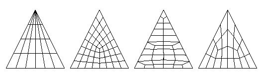
These are patterns for triangular macro
elements, where m3 = m2.
With pattern 134 all edges are equally
subdivided (m1 = m2 = m3) where m1 must be odd.
With Pattern 135 m1 must be odd and at least 1
and m2 must be at least 3 where m1 and m2 are independent of each other.
Pattern 136 is built upon 2 triangles by using
pattern 134. m1 must be at least 3. Correlation between m1 and m2 is given by
m1 = 2*m2+1 where m2 must be odd. Only m1 must be specified, m2, m3 are
automatically set to m3 = m2 = (m1-1)/2. Pattern 136 especially may be useful
when subdividing a semicircle area modeled by elements of type 32 into quadrilateral
elements.
Pattern 134 is the default when subdividing
macro elements of type 30-35, 60-65
Pattern
142
This pattern allows specifying independent
numbers of intermediate nodes for all edges of the underlying macro element. If
the sum of all intermediate nodes on edges is even for quadrilateral elements
or odd for triangular elements, exclusively quadrilateral elements are
generated. In the other cases one additional triangular element is generated.
Pattern
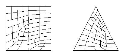
150 for triangular and quadrilateral macro elements with curved edges
As with pattern 142 the number
of intermediate nodes may be different for all edges. But with ID 150 the
geometry of the macro element is taken into account for the definition of the
pattern. The macro element is projected on a plane defined by the three first
corner nodes of the macro element. The triangular or quadrilateral element in
this plane is than subdivided using the algorithm described below for element
type 400. This net is then mapped to an unit element and this pattern is
further mapped to the geometry of the given macro element. The condition must
be met, that the quotient of greatest to smallest FE edge length is not greater
than 4.
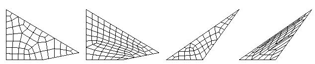
Pattern 150 should be used instead of pattern 142 when the angle of some
corners of the macro element differ greatly from 90 degree. Following pictures
show the differences of pattern 150 (left) and pattern 142 (right) for a
quadrilateral and a triangular element.
Pattern for element type 105
Macro element type 105 is a planar element with
up to 10 edges consisting of straight lines, circular arcs or spline curves.
For each edge the subdivision must explicitly be specified using the commands Division or Pattern.
With Pattern the following subdivision patterns
can be applied.
Pattern 150
This
invokes a free mesh generation as with element type 400 (see below).
Pattern 40
or 142
These
patterns can be used if 4 vertices of the polygon can be identified as corner
nodes of a quadrilateral element. The first vertex of the polygon is always the
first corner of the quadrilateral element. The remaining 3 corner nodes can be
specified using the command Element definition and will be saved after the elements height. If no corner nodes are
specified these vertices of the polygon are automatically selected which give
the smallest inner angles.
Pattern 151
- 551:
These
pattern IDs can be used with macro elements of type 105 with 5 edges. At first,
the element is divided into two quadrilateral elements by a line from a corner
of the polygon to the middle of the opposite edge. The two resulting
quadrilateral elements are divided by using the pattern 142. The first digit of
the pattern ID tells, which vertex of the polygon is used for the division into
two quadrilateral elements. Following picture shows pattern 151 and 251 if
lower left vertex is the first element node.
Pattern
152-552:
The
pattern corresponds to pattern 151-551 with the difference that conditions for
subdividing the edges 3 and 4 must be so that a regular subdivision with
quadrilateral elements can be achieved. These conditions are: m4 = m2 and m3 =
m1 + m5 + 1; m4 and m3 are corrected if they don’t meet this condition. The
first digit specifies which vertex will be the starting vertex for subdivision
into 2 quadrilateral elements. Following picture shows pattern 152 and 252 (see
also demo “pattern15x.dem”).
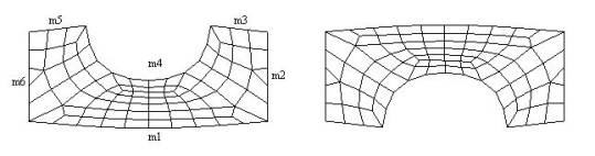
Pattern
161-661:
This
pattern corresponds to pattern 151-551. It can be used for elements with 6
edges. The element is first subdivided into three quadrilateral elements, which
are then subdivided by pattern 142. The first digit of the pattern ID tells
which vertex of the polygon will be the starting vertex for division into three
quadrilateral elements. Following picture shows pattern 161 and 561 if the lower left vertex is the first node of the
element.
Pattern
162-662
The
pattern corresponds to pattern 161-661 with the exception that conditions for
subdivision of edges 4 and 5 must be so, that a regular subdivision to
quadrilateral elements can be achieved. These conditions are: m5 = m3 and m4 =
m1 + m2 + m6 + 2; m5 and m4 are automatically corrected if they do not meet
these conditions. Following picture shows pattern 162 and 562.
Subdivision
of type 400 elements, pattern 150
Macro element type 400 is a planar element with
up to 39 edges consisting of straight or circular lines. For subdivision of the
element into finite elements, the edge length of the finite elements to be
generated must be given using command Division.
First the surrounded border of the element is subdivided using this value.
Beginning at the borders, quadrilateral and triangular elements are created until
the whole area is meshed. If the number of intermediate nodes on all edges is
odd, subdivision is done using the double edge length, then all quadrilateral
elements are subdivided into 4 and all triangular elements are subdivided into
3 quadrilateral elements; so one gets only quadrilateral elements. This first
subdivision with double edge length is only applied, if strongly curved edges
have at least 3 intermediate nodes.
Using command Pattern it is also possible to give the
number of intermediate nodes for all macro element edges in counter clock wise
direction, but the quotient of largest to smallest FE edge length must not be
greater than 4. The whole area is meshed using a FE edge length that is equal
to the mean value of the length given for all macro element edges.