Node forces: Define and assign forces and
displacements on nodes
Each force or displacement is defined by 3
vector components. A single force can be assigned to multiple nodes. Parameters
of the force definition and the assignments to nodes are saved within a single
load group. Each group will be assigned 2 IDs to identify it: one index and one
load set ID. The load set ID can be identical for several groups; it will be
saved within the PATRAN and NASTRAN interface and can be used by the FE program
for example as an ID for a load case. Each group however has its own unique
index. This index isn’t saved by the PATRAN or NASTRAN interface; it only
serves as an identification of load groups when defining loads. All values
saved under such an index can be deleted at all and newly redefined. After
saving such a group the index for the next group is automatically increased by
1. If an index of an already defined group is entered within the input field,
all the corresponding values of this group are shown within the relevant fields
of the dialog by pressing button “Show values”, so these values can easily be
modified, plotted or removed. The button „New index“ causes a new index to be
created.
The vector components may be specified in
reference to a local coordinate system (for example radial loads within a
cylindrical coordinate system). This coordinate system has to be defined
before; the ID of the system has to be given. When the PATRAN or NASTRAN file
is created all vectors defined within a local coordinate system may optionally
be transferred to the global system.
The button „Apply“ saves the specified forces
definition. In case there are already values stored with this index it will be
asked for overwriting. Answering „No“ will cancel this operation and the old values
are kept. By pressing button „Delete“ saved values with the shown index are
deleted. Pressing „Plot“ does a plot of the vectors.
After invoking this command the following
dialog is popped up with the shown options available. The dialog remains active
until it’s explicitly closed with button „Cancel“.
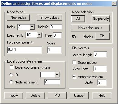
Node forces
Index:
The index of an already defined or a new load group must be given. A given
number greater than the largest used number + 1 automatically reduces the
number to this value.
New index:
Next available index is set in the input field.
Index2:
For the buttons „Delete“ and „Plot“ an upper limit of a range of indices can be
given in this input field.
Show values:
Pressing this button, the stored values of the group with the given index are
displayed in the different input fields.
Load set ID:
A load set ID must be given. Within the list box all previously used IDs are shown.
It’s possible to assign an already defined load set ID to a new load group.
Type:
With a type ID, different types of vectors can be distinguished. For the
NASTRAN interface the following type IDs are to be used: 0 = node force, 1 =
node moment, 2 = node displacement, 3 = node rotation.
Force components: Up to 3 values can be given. Lacking values are set to 0.
Scale:
For the NASTRAN interface a scale factor can be given in the input field.
Local
coordinate system
Local coordinate system: The option has to be set, if vector components are given in reference
to a local coordinate system.
ID: In
case of a definition of the vector components within a local coordinate system
the ID of this system must be given here. Within the list box all available IDs
are shown and can be selected. ID 0 is used for the global coordinate system.
Node increment: In case the loads are defined within local coordinate systems, which
were created by the option „Boundary curve“ within command Coordinate System,
the increment must be given which was used when defining the coordinate
systems.
Node
selection
These
nodes must be selected to which the given vector should be assigned. The IDs of
these nodes are stored with the load group.
Plot
vectors
Vector length: The length for displaying the largest saved
vector must be given.
Superimpose:
With this option set a new display list will be used for plotting, so it’s
possible to plot the vectors of different groups together by using different
colors.
Color index:
With different color indices different load groups can be distinguished
graphically.
Plot
The
button invokes a plot of the vectors of all groups within the given range of
indices.
Delete
Pressing
the button deletes all stored data for the given range of indices.