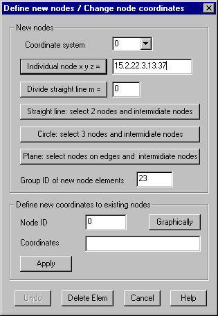
Define nodes: Define new nodes
With this command additional nodes used for
later element definitions by command Define Elements, can be created. Node coordinates must be given within the following
dialog. The dialog remains active until it’s explicitly closed by pressing
„Cancel“.

Coordinate
system
In case a
local coordinate system is selected, all given coordinates are related to this
system, applicable with options "Individual node" and “Divide
straight line”.
Individual
node
Coordinates in the selected coordinate system
of an individual node have to be given in the input field.
Subdivide
straight line
Pressing this button one or more straight
lines are equally divided. The number of intermediate nodes on the line must be
given in the input field. After pressing the button, 2 nodes as endpoints must
be selected for each line. In case a local coordinate system is selected, the
endpoints are transformed into the local coordinate system before the
subdivision is done, so the new nodes are generated in this coordinate system.
This way it is easy to get intermediate nodes on a cylindrical or a toroidal
surface, but it is important, that the angle of the endpoints lie in the range
0° to 360°. Otherwise the new nodes might lie
on the wrong half to the circle.
Straight
line
Pressing
this button, 2 nodes as end points of a line must first be graphically
selected. A straight line is drawn colored. After that the positions of new
nodes on this line have to be set by cursor (left mouse button). The right
mouse button ends the creation of new nodes on the line, and a new line can be
selected until the right mouse button is pressed twice.
Circle
Pressing
this button, 3 nodes on a circle have to be selected first. The circle will be
drawn colored. After that the positions of new nodes on the circle have to be
set by cursor. The right mouse button ends the creation of new nodes.
Plane
Pressing
this button, several existing nodes on the edges of a plane area must first be
selected graphically. These edges are plotted as an orientation. The first,
second and last node of the edges are used to define the plane, the angle
between these node should be near 90°. The selection of nodes is
interrupted with the right mouse button. After the edges are drown, the
position of several new nodes on the plane can be specified with cursor until
the right mouse button in pressed. For the graphic, parallel projection must be
selected; otherwise the calculated position of the new nodes might differ from
the cursor position. If the view is varied while new nodes are defined, the
determining points of the plane must remain in the graphics window.
Group ID of
new node elements
Nodes
created by this command will be assigned a node element. Within this input
field the group ID for these elements can be given.
Define new
coordinates to existing nodes
Node ID:
The ID of an existing node must be given. Pressing button “Graphically” a node
can be selected graphically by cursor, the ID and coordinates of the selected
nodes are shown in the dialog.
Coordinates:
The new coordinates of the node must be given in the input field.
Apply:
Pressing this button the new coordinates are stored in the data structure.
Undo
Pressing
this button, last created new nodes are deleted.
Delete
elements
Clicking
this button, the dialog for deleting elements pops up.