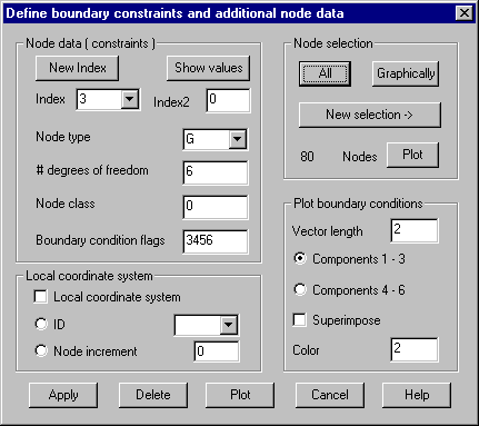
Constraints: Define and assign constraints on
nodes and additional node data
With this command constraints and additional
node data are defined, that are saved within PATRAN interface as „Node Data“.
For all nodes with no associations made the following defaults apply (within
parentheses the related PATRAN variable is shown)
Node type
(GTYP): G (structural nodes)
Number
degrees of freedom (NDF): 6
Node
class (CONFIG): 0
Coordinate
system (CID): 0
Constraint
flags (PSPC): 000000
With the NASTRAN interface, only the boundary
condition flags and the local coordinate system are used, these values are
stored optionally in the GRID records or in SPC1 records.
Different definitions are identified by a
sequenced index. The values defined under such an index can be completely
deleted and new defined. After saving a definition the index is increased by
one. After entering an already defined index all associated values are shown
within the dialog after pressing button “Show values” and can be deleted or
plotted. Button „New index“ gives the next unique index. The constraints can be
defined within a local coordinate system (for example radial components within
a cylindrical coordinate system). The coordinate system must have been already
defined.
Button „Apply“ saves the specified values for
this definition. If there are already values stored under this index it will be
asked for overwriting. Button „Delete“ deletes already saved values. Button
„Plot“ plots boundary condition. The dialog remains active until it’s explicitly
closed by „Cancel“.
Following Dialog shows the available options:

Node data
(constraints)
Index:
The index of a new or of an already saved definition must be given.
New index:
Next available index is set.
Show values:
The values of an already saved definition are displayed in the dialog.
Index2:
The upper limit of a range of indices to be used by „Delete“ and „Plot“ can be
given.
Node type:
G, A, F, T for PATRAN interface.
# Degrees of freedom: The number of DOF for the nodes must be given.
Node class: Class ID for separating between node classes
corresponding PATRAN interface can be given.
Boundary condition flags: A number consisting of the digits
1-6 must be given (for example the number 1346 stands for the flags 101101).
Local
coordinate system
Local coordinate system: The option has to be set if the constraints are referring to a local
coordinate system.
ID: The
ID of an already defined coordinate system can be given (ID = 0 means global
coordinate system). All currently defined coordinate systems are shown within
the list box.
Node increment: If the constraints are defined for a local
coordinate system which was defined using option „Boundary Curve“ in command Coordinate System the same increment as for the
definition of the coordinate systems has to be given here.
Node
selection
The node
selection must be given on which the boundary conditions should be applied.
Plot
boundary conditions
Vector length: Max. length of plotted vectors must be given
Components 1-3 / 4-6: Select which components should be plotted. Translations (1-3) or
rotations (4-6).
Superimpose:
With this option set the previously used layer won’t be deleted prior to
plotting, so it’s possible to do multiple plots using different colors.
Color:
Give the color index to use for plotting the vectors.