Check elements: Check angles, orientation, etc.
Some checks on
the finite element structure are done. The IDs of all the elements, which
haven’t passed these tests, are saved as a new element selection set, these
elements can also be graphically marked. This set can be modified later, for
example by applying the command Type2Type
for converting 4-node elements with very large or very small vertex angles into
two 3-node elements.
The dialog
remains active until pressing „Cancel“ closes it. After specifying the
parameters the check is started using „Apply“.
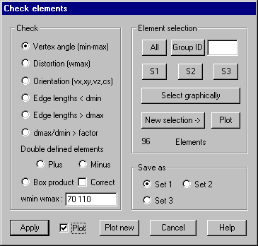
Following dialog
shows the available options:

Check
Vertex angle (min-max): Vertex angles of all selected elements are checked against the smallest
and the largest permitted value, that have to be given in the input field.
Distortion (max): Distortion of 4-node elements is checked by
calculating the angle between the normals in node 1 and 3 of the element.
Maximum permitted value has to be given.
Orientation (vx,vy,vz,cs): The scalar product for the normal of the
element and the given vector is calculated and checked for a positive sign. For
all elements with negative results it’s asked for turning the orientation in
the opposite direction by reordering the vertices. Optional parameter cs can be
the ID of a local coordinate system. In this case the orientation is calculated
within this system.
Edge length < dmax: All elements are checked against an edge length lower than the given
value.
Edge length > dmax: All elements are checked against an edge length greater than the given
value.
dmax/dmin > fact: The ratio of the largest and the smallest edge
length is calculated and checked against the given value.
Double defined elements: All elements are checked against each other whether there are elements
with identical vertices. For this check it’s distinguished between equal
(Option “Plus”) or opposite (Option “Minus”) direction. In case double defined
elements are found, the IDs of these elements are saved under Set1 and Set2. By
selecting one of these sets afterwards the related elements can be removed with
the command Delete. Please note that only surface
elements are checked.
Box product:
Box product (triple scalar product) for solid elements is checked at all
corners for equal sign. The sign is taken from the first solid. If option
„Correct“ is marked the orientation of elements with a negative box product is
automatically corrected.
Input field:
Within this input field the numerical values for the above selected check must
be given, angles are to be given in degrees.
Element
selection
Only
selected elements are checked.
Save as
Select
the set (1 to 3) into which the IDs of the elements, which don’t pass the
checks, should be stored
Plot
With this
option set all elements that do not pass the check are shown graphically by
using a distinct color.
Plot new
This
refreshes the graphics